
HVAC Electrification Strategies
Heating, cooling, and air-conditioning (HVAC) system electrification is one of the most recommended pathways to building decarbonization. Electrification allows you to transition from fossil fuels to using clean, renewable electricity and energy storage.
How to Evaluate Electrification Strategies
Reduce Loads First
Before switching to electric-powered equipment, implement energy-conservation measures to reduce your energy consumption. Then assess the newly reduced building loads either directly or using an energy model. Reducing energy consumption to the extent possible will help you achieve comfortable interior conditions, appropriately size the new HVAC equipment being installed, and save on initial and operating costs.
Consider Capital Replacement Planning Schedules
Most HVAC equipment has a limited lifespan. When evaluating electrification strategies, review the campus master plan, assess the renovation cycles of your buildings, evaluate options for all-electric equipment replacements and determine the space you have available for new equipment. To minimize disruption to service and get the best use out of existing functioning equipment, aim to replace gas-fired equipment at the end of its life with an electric option.
Evaluate Your Campus’ Electrical Capacity
Decarbonization through electrification will increase electrical demand, potentially exceeding the capacity of existing circuits and electrical panels.
Assess the capacity of existing infrastructure and individual buildings slated for electrification to confirm that new all-electric equipment options are within current electrical capacity.
Engage the electrical utility early in these conversations. If an upgrade is needed, consider other projects that should be included to reduce the overall costs of the transition.
Consider Spatial and Structural Requirements
Electric HVAC technologies may have additional spatial and structural needs. For example, air source heat pumps have large airflow needs that require them to be installed outdoors or within a space with sufficient airflow.
Consider the weight, spatial, and structural requirements and consider a structural engineer to assess the added load and structural capacity of the new installation location. Larger assemblies may also require concrete pads and other structural reinforcements.
Available Electric HVAC Technologies
Heat Pumps
Heat pumps use refrigerant to transfer heat from sources such as water, air, or the ground for space or water heating. This process is reversed to offer cooling during warmer months. Following are some basic types of heat pumps:
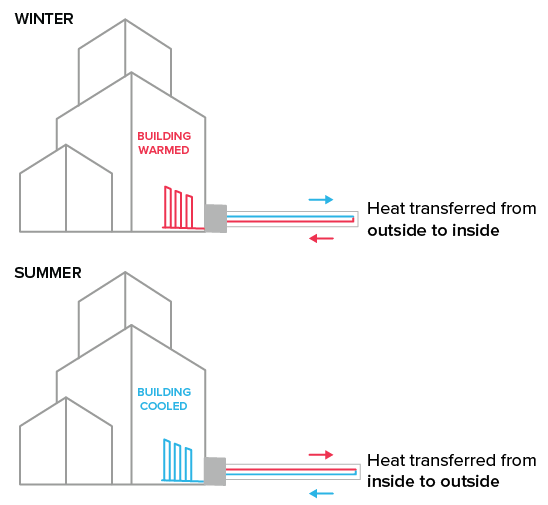
Air-source Heat Pump
This graphic depicts the two modes of an air-source heat pump system for year-round climate control. It shows the flow of thermal energy being extracted from outdoor air to heat the building in winter and being released outside to cool the building in summer.
Ground-source heat pumps (GSHPs) provide heating and cooling year-round regardless of outside temperatures by leveraging the stable underground earth temperatures. Though they have high first costs, GSHPs often have lower long-term operating costs than other systems as they have fewer moving parts requiring replacement. A GSHP system includes a heat pump and a ground heat exchanger (e.g., bore field), and is ideal for both standalone buildings and district energy system approaches. GSHPs are ideal for regions with substantial seasonal temperature variations such as New York.
Learn more about how to perform a geothermal conversion.
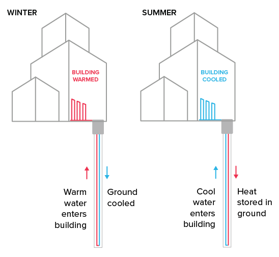
Ground-source Heat Pump
This graphic depicts a ground-source heat pump system that utilizes stable underground temperatures for climate control. During winter, the system extracts heat from the earth to warm the building, while in summer, it transfers heat from the building back into the ground for cooling.
Variable refrigerant flow (VRF) heat pumps can be ground- or air-sourced. They provide simultaneous heating and cooling needs within a building. These work best in tandem with heat recovery chillers (see below).
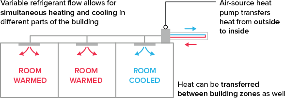
Variable Refrigerant Flow
This graphic depicts a variable refrigerant flow (VRF) heat pump system capable of simultaneous heating and cooling across different building zones. It shows how the system can transfer heat from the outside to the inside while also redistributing thermal energy between individual rooms.
- Variable refrigerant flow allows for simultaneous heating and cooling in different parts of the building
- Air-source heat pump transfers heat from outside to inside
- Heat can be transferred between building zones as well
Refrigerants
Refrigerant choice matters in heat pump system design. Up until now, commonly used refrigerants such as R-32 and R-410A have relatively high global warming potential (GWP), but these are being phased out.
Manufacturers and system designers are increasingly transitioning “natural refrigerants” such as carbon dioxide (CO2), ammonia (NH3), and synthetic options. Specifying heat pump systems with low-GWP refrigerants supports climate goals, ensures compliance with forthcoming regulatory standards, and mitigates the risk of equipment replacement due to outdated refrigerants.
Heat-Recovery Chillers
A heat-recovery chiller is an advanced system that offers both cooling and heating capabilities while maximizing energy efficiency by recovering waste heat generated during the cooling process. This can be used for building heating, service water heating, and process heat applications.
Heat-recovery chillers are most suitable for buildings or in campus loops that have simultaneous heating and cooling demands, such as laboratories, supercomputing centers, hospitals, food service, and residential complexes.
There are two common types of heat-recovery chillers:
Water-cooled heat-recovery chillers capture waste heat generated during the cooling process and redirect it to a heat exchanger. This recovered heat is transferred to a water loop for reuse in applications such as space heating and domestic hot water.
- Single-condenser heat-recovery chiller is most similar to a conventional chiller. It is common to pair these chillers with a heat exchanger to separate the cooling tower and the chiller.
- Dual-condenser heat-recovery chiller has two separate condensers with one dedicated to the heat recovery process. They can operate in cooling only if required.
Air-cooled heat-recovery chillers produce chilled water while generating hot water as a byproduct. In normal cooling mode, they function like standard air-cooled chillers, rejecting heat to the environment. In heat recovery mode, they provide both chilled and hot water simultaneously, maintaining the chilled water temperature setpoint while producing as much hot water as possible. The system adjusts based on the hot water setpoint, activating circuits to meet heating needs when the hot water temperature falls below the setpoint.
Thermal energy storage (TES) systems can be integrated during low heating loads. The TES stores excess heat, ensuring efficient operation and maximizing the benefits of the heat recovery chiller even when the demand for heating is inconsistent.
Coefficient of Performance (COP)
The efficiency of a technology type is measured in coefficient of performance (COP), which is the ratio of one unit of a power source consumed to units of heat produced. More simply, it is expressed as:
COP = useful heat output ÷ energy input
For instance, a standard gas furnace has a coefficient of performance (COP) of around 0.8 to 0.9—meaning it converts 80–90% of the energy in natural gas into usable heat, while the rest is lost. Electric resistance offers a slight improvement with a COP of 1.0 (100%). A modern electric heat pump can achieve a COP of 3.0 (300%) or higher.
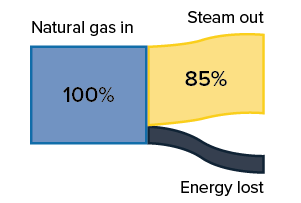
Steam generated compared to natural gas burned.
- Natural gas in: 100%
- Steam out: 85%
- Energy lost: 15%
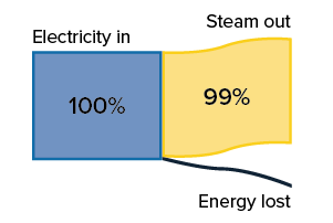
Steam generated compared to electricity used.
- Electricity in: 100%
- Steam out: 99%
- Energy lost: 1%
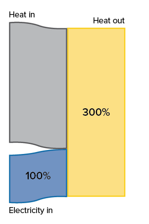
Heat generated compared to electricity (and free, ambient heat) used.
- Heat in
- Electricity in: 100%
- Heat out: 300%
Planning and the Bigger Picture
Tackling an HVAC electrification project requires reviewing and assessing existing energy loads and evaluating potential technologies. While design and installation look different for each campus and for each of the technologies mentioned above, they all require some level of planning to succeed.
The feasibility of any HVAC electrification strategy depends on a review of installation locations, the building’s existing electrical capacity, potential access to low carbon thermal resources, and the space, weight, and airflow requirements of each technology. Also helpful is sequencing and ensuring that overlapping projects do not conflict with each other in a decarbonization pipeline.
While electrification strategies may have higher upfront costs than a fossil-fuel option (sometimes along with increasing electricity usage within a building), overall energy use and utility bills will typically be lower for electrified options due to increased efficiency and the reduced size of the systems. Be sure to perform a life-cycle cost analysis on all available options before making any decisions.
Resources
- U.S. Department of Energy’s Better Buildings Solutions Center: Energy Efficiency

- U.S. Department of Energy: Heat Pump Systems
- U.S. Environmental Protection Agency’s ENERGY STAR: Air-Source Heat Pumps
- U.S. Department of Energy’s Better Buildings Solutions Center: Decarbonizing the Commercial Kitchen
- NYSERDA: Clean Heating & Cooling Reports
- U.S. Department of Energy’s Better Buildings Solutions Center: Utilization and Energy Storage
- Storage Strategies
Connect With Us
Discover how to achieve large energy and carbon reductions across your campus.
Get In Touch