
District Energy Strategies
On This Page:
District energy (DE) systems use a piping network to distribute thermal energy to multiple buildings from a central source to provide space heating, water heating, cooling, or process loads. DE systems, also referred to as thermal energy networks (TENs), are in operation at many campuses; some for over a century. DE systems can be an important strategy to help decarbonize a campus as compared to a decentralized (individual building level) approach.
Whether your campus already has DE or not, when moving to decarbonize, a campus should understand the attributes of DE systems that can enhance cost effectiveness, flexibility, and resilience in the transition. An outcome of the decarbonization planning process may be installation of a new DE system or adaptation or expansion of an existing DE system.
District heating (DH) systems are DE systems that provide heating. DH systems are sometimes categorized into ‘generations’ that signify operating temperatures, typical heat sources, and other characteristics. Although there are no strict definitions, Table 1 lists the generations along with typical supply temperatures and media. Note that some systems in the table also provide district cooling (DC).
Many existing DE systems are earlier generation (1st through 3rd generation). The high heating supply temperatures in these earlier generations make it challenging to apply heat pumps, which are commonly used to decarbonize heating systems. High temperatures can be achieved by heat pumps but at greater capital and operating expense and lower efficiency. It is more common when applying heat pumps to pair them with 4th or 5th generation systems. Where earlier generation DE systems already exist, converting to, or replacing with, a 4th or 5th generation DE system is possible, but the requirements and cost can be substantial and require planning. This chapter focuses on 4th generation and ambient DE systems, including comparisons between them and also to decentralized buildings.
| Designation | Description |
|---|---|
| 1st Generation District Heating |
Steam 2-pipes (steam and condensate) |
| 2nd Generation District Heating |
Pressurized hot water above 100°C (212°F) 2-pipes (hot water supply and return) |
| 3rd Generation District Heating |
Hot water, below 100°C (212 °F) 2-pipes (hot water supply and return) |
| 4th Generation District Heating |
Low temperature hot water typically below 82°C (180°F) 2-pipes (hot water supply and return) |
| 4th Generation District Heating & Cooling |
Low temperature hot water typically below 82°C (180°F) 4-pipes (hot water supply and return, chilled water supply and return) Like 4GDH but combined with a cooling network |
| Ambient Loop District Heating & Cooling |
Ambient water or glycol typically 0-30°C (32-86°F) serves as heating source or cooling sink for building heat pumps Can be 1-pipe (combined supply and return) or 2-pipe (separate supply and return) Heating and cooling provided by building-level heat pumps |
District Energy Components
A DE system has three main elements: thermal energy production, the distribution network (piping), and the building connections. Other components, like thermal energy storage, can be added to enhance the economics and operation of DE systems.
Thermal Energy Production
Buildings in a DE system get their thermal energy from an external source. Historically that might have been from a central heating or chilled water plant, sometimes referred to as energy center(s). For a fully centralized (1st through 4th generation) system, the energy center includes pumps, but also energy conversion equipment (e.g., boilers, heat pumps, chillers) that produce the heating medium and cooling medium at the final delivery temperature to the buildings. In an ambient loop system, the building heating and cooling energy is met in part by building level heat pumps and in part by thermal energy sources connected to the loop (e.g., geothermal borefields, waste heat sources). Energy center(s) in an ambient loop include pumping stations and can also include loop balancing equipment.
Where heat pumps are part of the energy conversion equipment, they require a thermal source. The same thermal sources can be used for 4th generation systems as for ambient loops. Potential thermal sources include ambient air, geothermal boreholes, surface water, and various waste heat sources (e.g., heat rejection from space cooling or data center cooling, wastewater). The decarbonization plan should focus on what thermal sources will best suit the campus.
Distribution Network
Distribution networks carry thermal energy from the energy center to buildings to meet heating and/or cooling needs. For network types that provide heating only, cooling is decentralized (building level equipment). Since cooling systems are most often electrically driven already (or easily converted), the choice of centralized vs decentralized cooling is typically cost driven. Table 1 described the main differences between common network types, including the distribution media and temperatures. The type of network a campus chooses will affect installation and operating costs, future campus projects, and flexibility and resiliency. Table 2 includes an expanded description of the 4th generation and ambient loop networks.
| Distribution Network Piping Configuration | Description |
|---|---|
| 4th Generation District Heating, 2 -Pipe |
|
| 4th Generation District Heating & Cooling, 4-Pipe |
|
| Ambient Loop District Heating & Cooling, 1-Pipe |
|
| Ambient Loop District Heating & Cooling, 2-Pipe |
|
Building Interface
The connection between the distribution network and the buildings can vary. Some connections directly use the distribution medium that is circulated within the network; others incorporate an energy transfer station (ETS), which hydraulically decouples the building systems from the district and allows for operating at different temperatures and pressures (or even different circulation media as is sometimes seen with district steam networks that feed buildings that convert the steam to hot water for use in the building).
On many hydronic (hot water) DE systems, each building connects to the DE system through an ETS. The ETS includes heat exchangers, control valves, differential-pressure controls, and local circulation pumps to modulate energy delivery to match the building’s demand. Thermal meters may be installed to measure flow and temperature to compute energy for billing and analytics.
In some DE arrangements, such as district CHW systems, the water from the distribution system can flow directly into the building system through control valves and without the heat exchanger of an ETS. An advantage to this arrangement is that there is no supply temperature degradation across the heat exchanger. Some ambient loop systems utilize a direct connection without ETS to avoid supply temperature degradation.
Some specialty systems or process loads may require special treatment if they cannot be easily connected to the DE system. An example may be steam sterilizers in a lab that are fed by a district steam system but may require a stand-alone steam generator after the building becomes part of a decarbonized DE system.
Thermal Energy Storage
Thermal energy storage (TES) in DE systems enables heat or cooling production to be decoupled from the real-time load requirements by generating excess heat or cooling at times of lower generation cost or excess generating capacity and using that thermal energy at times of higher generation cost or limited generation capacity. The ability to shift these loads can reduce capital and operating expenses, reduce electrical demand, and provide flexibility and resiliency. TES is commonly paired with centralized systems (e.g., 4th Generation) using technologies such as stratified hot or chilled water tanks, ice storage, or subsurface options like borehole thermal energy storage (BTES) and aquifer thermal energy storage (ATES). These systems can be designed to be used in a dispatchable manner for partial peak shaving or full load shifting and are most cost effective at a large scale.
TES can be employed in ambient loop systems, but if it is incorporated on the loop it does not appreciably affect electrical loads because the building heat pumps still need to operate to meet instantaneous loads. TES can be incorporated at the individual building level to shift heat pump operation, but it is less cost-effective to install many small TES tanks than a large centralized one.
Simplified DE System Schematic Examples
Figures 1 through 4 show graphical representative examples of 4th generation and ambient loop DE systems.
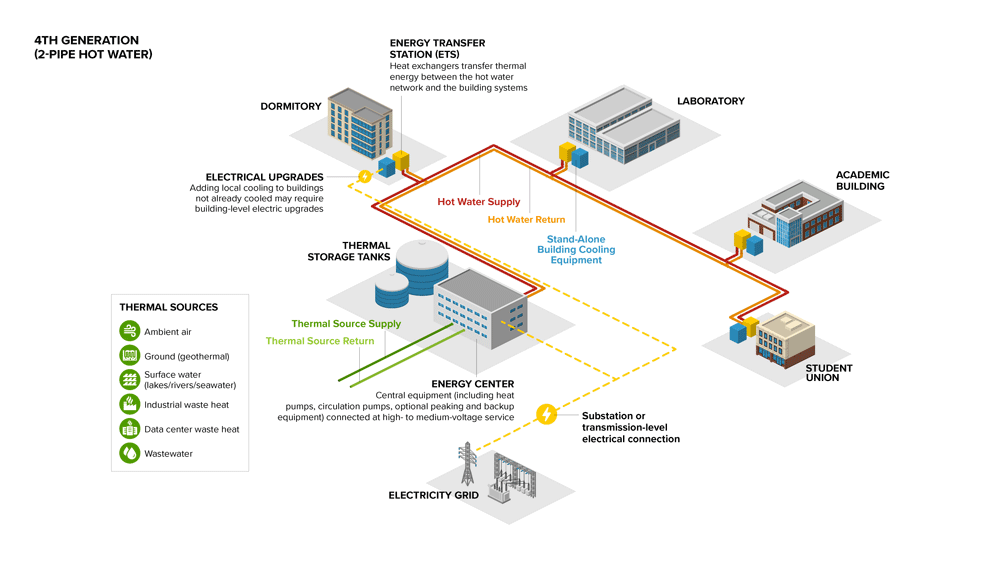
Figure 1. 4th Generation District Heating Network (2-Pipe)
This figure depicts a 4th Generation District Heating Network 2 (two) pipe hot water system. It shows a thermal energy source (Ambient Air, Ground (geothermal), Surface Water (lakes/rivers/seawater), Industrial Waste Heat, Data Center Waste Heat, or Wastewater) supply entering the Energy Center connected to Thermal Storage Tanks. An Energy Center includes Central equipment (heat pumps, circulation pumps. Optional peaking and backup equipment) connected at high-to-medium voltage service. From there, a Hot Water Supply line is distributed to Energy Transfer Stations (ETS) at multiple buildings (dormitory, laboratory, academic buildings, student union) on a college campus. An ETS is where Heat Exchangers transfer thermal energy between the hot water network and the building systems. Each of these buildings has it’s own Stand-Alone Building Cooling Equipment next to the ETS. A Hot Water Return line at each building then distributes water back from the ETS to the Energy Center. At the dormitory and energy center, a yellow dotted line indicates an electrical upgrade from the electricity grid connected to a substation or transmission-level electrical connection. When adding local cooling to building that are not already cooled, they may requirement building-level electrical upgrades.
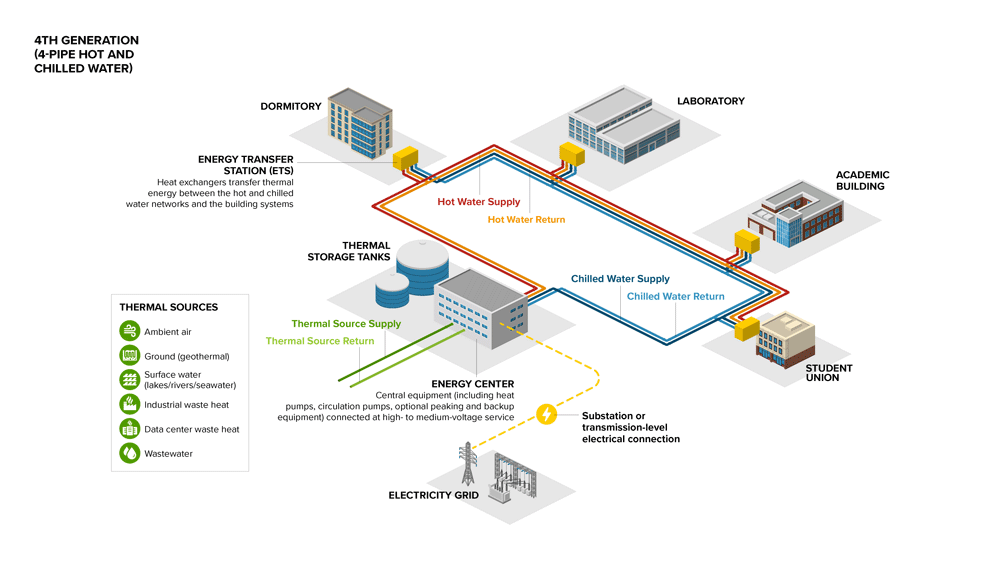
Figure 2. 4th Generation District Heating & Cooling Network (4-Pipe)
This figure depicts a 4th Generation District Heating Network 4 (four) pipe hot water system. It shows a thermal energy source (Ambient Air, Ground (geothermal), Surface Water (lakes/rivers/seawater), Industrial Waste Heat, Data Center Waste Heat, or Wastewater) supply entering the Energy Center connected to Thermal Storage Tanks. There is a thermal source return line from the Energy Center, as well. An Energy Center includes Central equipment (heat pumps, circulation pumps. Optional peaking and backup equipment) connected at high-to-medium voltage service. From there, a Hot Water Supply line and Chilled Water Supply line is distributed to Energy Transfer Stations (ETS) at multiple buildings (dormitory, laboratory, academic buildings, student union) on a college campus. An ETS is where Heat Exchangers transfer thermal energy between the hot water network and the building systems. Each of these buildings has it’s own Stand-Alone Building Cooling Equipment next to the ETS. A Hot Water Return and Chilled Water Return line at each building then distributes water back from the ETS to the Energy Center. At the dormitory and energy center, a yellow dotted line indicates an electrical upgrade from the electricity grid connected to a substation or transmission-level electrical connection.
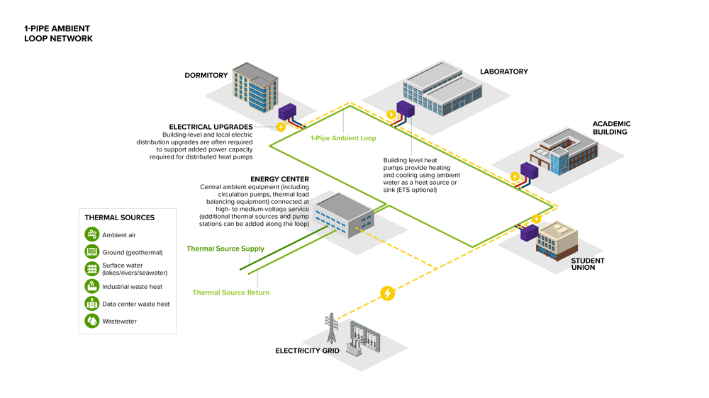
Figure 3. Ambient Loop Heating & Cooling Network (1-Pipe)
This figure depicts an ambient loop heating and cooling network 1 (one) pipe system. It shows a thermal energy supply source (Ambient Air, Ground (geothermal), Surface Water (lakes/rivers/seawater), Industrial Waste Heat, Data Center Waste Heat, or Wastewater) entering the Energy Center. The Energy Center contains central ambient equipment (including circulation pumps, thermal load balancing equipment) connected at high-to-medium voltage service (additional thermal sources and pump stations can be added along the loop). From the Energy Center, ambient water is distributed to building level heat pumps at multiple buildings (dormitory, laboratory, academic buildings, student union) via 1-Pipe Ambient Loop on a college campus. Each building has its own heat pumps, which provide heating and cooling using ambient water as a heat source or sink (ETS optional). This ambient water is then returned from the heat exchangers to the Energy Center. At the Student Union, Academic Building, Laboratory, Dormitory, a yellow dotted line indicates an electrical upgrade from the electricity grid connected to a substation. Building-level and local electric distribution upgrades are often required to support added power capacity required for distributed heat pumps.
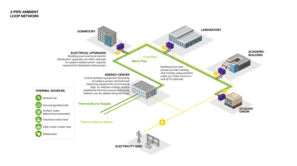
Figure 4. Ambient Loop Heating & Cooling Network (2-Pipe)
This figure depicts an ambient loop heating and cooling network 2 (two) pipe system. It shows a thermal energy supply source (Ambient Air, Ground (geothermal), Surface Water (lakes/rivers/seawater), Industrial Waste Heat, Data Center Waste Heat, or Wastewater) entering the Energy Center. The Energy Center contains central ambient equipment (including circulation pumps, thermal load balancing equipment) connected at high-to-medium voltage service (additional thermal sources and pump stations can be added along the loop). From the Energy Center, a warm pipe and cold distributes water to building level heat pimps at multiple buildings (dormitory, laboratory, academic buildings, student union) via 1-Pipe Ambient Loop on a college campus. Each building has its own heat pumps, which provide heating and cooling using ambient water as a heat source or sink (ETS optional). This ambient water is then returned from the heat exchangers to the Energy Center. At the Student Union, Academic Building, Laboratory, Dormitory, a yellow dotted line indicates an electrical upgrade from the electricity grid connected to a substation. Building-level and local electric distribution upgrades are often required to support added power capacity required for distributed heat pumps.
District Energy Comparison
4th Generation Network, Ambient Loop Network, and Decentralized Buildings
The different characteristics of the 4th generation system and ambient loop system – and the option of no network individual building systems – result in relative advantages and disadvantages to consider. A campus that chooses to implement DE may exclude some buildings from the network depending on cost effectiveness; especially smaller and/or distant buildings.
Table 3. shows some common characteristics of 4th generation and ambient loop DE systems. Specific implementations may vary, but the table illustrates the fundamental difference: 4th generation systems use centralized heating and cooling production, while ambient loop systems rely on building-level heat pumps connected to the network. This distinction affects how heating and cooling are delivered, how flexibility is achieved, and how different thermal sources can be integrated. The values in the table are typical. The building heat pumps in an ambient loop system provide both heating and cooling, whereas 4th generation systems require separate district cooling to provide both at a network level (except for the case of seasonal switch-over 2-pipe systems); otherwise, cooling is handled with building-level systems.
| Characteristic | 4th Generation Systems | Ambient Loop Systems |
|---|---|---|
| Primary Concept | Fully centralized, low temperature hot water to buildings; can be coupled with centralized district cooling | Thermal source network distributes ambient temperature fluid to building water-source heat pumps that generate heating and cooling |
| Number of Pipes |
2 (District heating only or seasonal switch over to cooling only) 4 (District heating and cooling) |
1 or 2 |
| Pipe Materials |
Insulated steel or high temperature polymer (Heating) Insulated polymer (Cooling) |
Uninsulated polymer |
| Typical Network Supply Temperature |
Heating: 50-70°C (122-158°F) Cooling: 4.5-10°C (40-50°F) |
0-30°C (32-86°F) ambient water or glycol (heating source or cooling sink) |
| Typical Network Delta-T |
Heating: >22° C (>40°F) Cooling: 6-11°C (10-20°F) |
3-8°C (5-15°F) |
| Pipe Dimensions | Smaller diameter piping due to high delta-T | Larger diameter piping due to low delta-T |
Comparing Performance Aspects
DE systems offer substantial advantages over decentralized building systems. Their implementation entails significant upfront capital investment, multifaceted coordination among various stakeholders, and phased development schedules. Thoughtfully planned and executed DE systems can provide efficient, flexible, and resilient solutions to campus heating and cooling needs. They can also support operation of the electric grid, reduce the need for electrical upgrades, and facilitate increased renewable electricity on the grid.
The differences between 4th generation and ambient loop systems, as well as decentralized setups, lead to trade-offs. Choosing the appropriate energy system for a campus impacts future operations and renovation projects. There's no universal solution, so it's advisable to develop a Decarbonization Plan tailored to your campus’ specific needs. This section describes some important performance aspects that pertain to decentralized or DE systems followed by a comparison in Table 4.
| Performance Aspect | Decentralized | 4th Generation Systems | Ambient Loop Systems |
|---|---|---|---|
| Energy Exchange | No energy exchange between buildings |
One-way thermal energy transfer Heat shared when paired with district cooling |
Thermal energy transfer between customers and with central thermal source |
| Thermal Sources for Heat Pumps | Examples: Ambient air, geothermal, and waste heat (local to the building) |
Examples: Ambient air, geothermal, and waste heat Proximity to the central energy center affects feasibility and cost Advantages:
|
Examples: Ambient air, geothermal, and waste heat Advantages:
|
| Distribution Thermal Losses | No network thermal losses | Losses greatly reduced from previous generations due to lower operating temperatures | Negligible thermal losses |
| Demand Flexibility, Redundancy & Resiliency |
Disadvantages: Building level systems are more difficult to apply demand flexibility approaches due to cost and space constraints |
Advantages: Central energy center facilitates:
|
Advantage: Thermal mass of the distribution system reduces peak demand compared to individual building heat pumps, but building-level thermal energy storage or non-electric assets required to actively manage heat pump electric demand Disadvantages: Building level systems are more difficult to apply demand flexibility approaches due to cost and space constraints |
| Capital Cost |
Advantages:
Disadvantages:
|
Advantages:
Disadvantages:
|
Advantages:
Disadvantages:
|
| Operational Cost |
Advantage:
Disadvantage:
|
Advantages:
Disadvantage:
|
Advantage:
Disadvantage:
|
Fundamental Design Aspects
Energy Exchange
The way energy is exchanged is fundamentally different in this comparison. Decentralized buildings do not exchange any energy amongst each other. There is a one-way exchange of useful thermal energy from an energy center to connected buildings in a 4th generation system; an exception is that 4th generation systems can accept heat rejection from buildings receiving district cooling, which is useful as a heat source for simultaneous heating. Inherent to their design, ambient loop systems permit a two-way transfer of thermal energy between buildings through the loop. This can be a significant benefit when buildings with complementary heating and cooling needs are served.
Centralized Equipment
DE systems incorporate centralized equipment that can afford certain benefits and simpler operations at this centralized level than at each building:
- Including hybrid supply approaches for base load and peaking technologies
- Installing non-electric heating technologies for emergency backup and to support the electric grid via demand response
- Installing thermal energy storage
- Installing new technology equipment that may be advantageous in the future (no need to disturb each building)
Expandability
DE systems can accommodate expansion to serve additional buildings and to add thermal resources – within the limits. The base design should anticipate the potential for additional future loads for key infrastructure like the network piping mains and space within the energy center. Ambient loop systems can add thermal sources (e.g., geothermal borefields and waste heat) to the main distribution system at any point in the loop, whereas 4th generation systems require that source to be piped to the energy center first.
Thermal Energy Resources
Both 4th generation and ambient loop systems can use the same thermal resources described previously. Individual buildings can use the same thermal resources as well, except some large-scale sources would be impractical at the individual building level (e.g., industrial waste heat).
Demand Flexibility
Demand flexibility describes the ability of the DE system to actively reduce or shift electrical demand to better manage electrical load, cost, or grid emissions. Demand can be shifted through strategies like energy storage or temporarily shifting to a non-electric heating source. Demand flexibility benefits the owner, electrical grid, and the decarbonization. DE systems can incorporate demand flexibility either inherently or by the addition of enabling equipment. The applicability and extent of demand flexibility depend on the type of DE system and the inclusion and capacities of enabling equipment.
Owner Benefits
The ability to reduce or shift electrical demand can reduce the operating expense for the owner by reducing electricity use when prices are high and limiting demand charges. It is also possible to reduce the peak equipment capacity for the electric heating sources, which can reduce capital expense.
Electric Grid Benefits
Demand flexibility benefits the electrical grid through the ability to actively reduce electrical demand during periods of high electrical demand. This makes grid management easier and reduces the need to add or maintain peaking electric generating plants.
Decarbonization Benefits
The ability to reduce or shift electrical demand helps facilitate decarbonization efforts for the campus and beyond. Shifting electrical demand away from peak periods tends to reduce operation of fossil fuel peaker plants, reducing carbon emissions. Also, having more dispatchable demand reduction on the electric grid increases the achievable fraction of interruptible renewable generation while maintaining load balance; thereby reducing grid emissions.
Expenses
Capital Expenses
There are many differences between DE system types that relate to capital expense.
Economies of Scale
DE systems include some components that are larger in scale than they would be for individual building systems; primarily the centralized components, which vary depending on the type of DE system. The cost per unit capacity of the larger equipment is lower, reducing capital expense.
Load Diversity
The aggregation of loads for all buildings connected to the DE system leads to a system peak load that is less than the sum of the individual building peak loads because they do not all occur at the same time. As a result, the capacity requirement for all centralized equipment is less than what the capacity would need to be if it were installed at the building level; this can reduce capital expense. Examples include thermal resources, centralized generation equipment, and thermal energy storage. Building heat pumps still need to be sized to meet the peak load of the individual building they are installed in, so the total installed capacity is higher than what would be required for centralized heat pumps.
Hybrid Approaches
Another way to reduce capital expense is to facilitate hybrid approaches to supplying the required thermal energy to the connected buildings. Heat pumps, and their associated thermal sources, are relatively expensive to install compared to traditional or electric resistance heating technologies. One approach to reducing capital expense is to size the heat pumps to approximately 40-60% of the peak load which may allow them to still meet approximately 90% of the annual load due to the shape of the heating load profile (systems operate near peak load limited hours per year). Less expensive heating equipment can be installed to make up the balance of peak capacity requirement, and that equipment would operate when loads are near peak. Hybrid approaches are easier and more cost-effective to incorporate for centralized equipment compared to distributed equipment. The same applies to emergency backup heating and thermal energy storage.
Distribution Network
Capital expense is highly impacted by the type of distribution network, and there are many factors that affect that cost such as: number of pipes, piping materials, insulation requirements, pipe diameter, trenching requirements, and installation methods. DE system choice and design parameters affect these aspects and associated costs. Pipes with higher delta-T (temperature difference between supply and return) can be smaller diameter but will also typically require insulation. Most network types start with large diameter pipes near the energy center and reduce to smaller and smaller pipes out to the furthest buildings, but 1-pipe ambient loops do require the piping main loop to be the same diameter. Also, trenching is a major cost component that does not scale directly with the number or diameter of pipes. All of these factors affect capital cost in different ways.
Building Interface
The interface between the buildings and the various DE systems are different and that also affects capital cost. The interface for a 4th generation system is typically limited to an ETS with heat exchanger because the generation equipment is centralized. For ambient loop systems, a heat exchanger may or may not be included, but building heat pumps are required as well as the space to install them.
Existing Building Modifications
Some existing buildings can be a challenge to decarbonize for any DE system as well as for an individual building approach; others are easier. The level of effort and expense will depend on the specifics of the existing building systems. For example, existing buildings that use steam directly or high temperature hot water will likely require major renovations regardless of decarbonization approach. The potential need for building electrical upgrades can be a capital cost that varies with DE system choice as well. Existing building modifications can be a major portion of the total cost to decarbonize a campus and deserves due scrutiny during the planning process.
Operating Expenses
Operating expense is another performance aspect to consider when choosing a DE system. The previous paragraph describing owner benefits from demand flexibility applies directly to operating cost. Another aspect of electricity rates that can apply is the potential difference in rate class for large central plant equipment as compared to building equipment. In a large district energy system, the central plant would typically operate on a large customer rate tariff as opposed to higher cost customer rates, though this might not be as applicable for a campus operating at a single large customer rate for all buildings. Maintenance is another operating expense that can vary, especially for large, centralized equipment versus distributed components.
Connect With Us
Discover how to achieve large energy and carbon reductions across your campus.
Get In Touch